


Markyboard
-
Posts
7,452 -
Joined
-
Last visited
Content Type
Profiles
Forums
Blogs
Events
Articles
Downloads
Gallery
Store
Posts posted by Markyboard
-
-
Yup - really enjoyed the virtual hang last night. Great seeing/chatting with all who participated.

-
I think it might be cool to have a VR interface for soft synths like Diva and such. Only I want the holodeck version where I don't need the idiotic ski mask and I can play a real physical controller. Wake me up when it's ready.
-
Per Dan Phillips tentative street price is $1599.
-
[video:youtube]
-
-
Very unhappy people. Secretly, they all want guitars...
Think again.
:saber: F'n twangsters.
-
I have heard (maybe here) that techs usually have a scanner ready to go and swap it for one that's motorboating, and then clean the motorboating one at the shop later. Then that's ready for a swap when he needs one.
You mean like this one sitting on my shelf for 3 years waiting to be cleaned?
-
I have recently done a scanner. Here's my experience:
A friend's '70 B-3 started motorboating. We did the battery zap and it fixed it for a day or two. We came back again with more batteries and zapped it with a higher voltage. No dice this time - only a scanner clean out would do.
It went pretty smoothly. It was my first, but I followed the excellent directions Benton provides (which I'll link below.)
I managed to remove the scanner from the motor and weasel it out to be disassembled, without removing manuals or disconnecting large harnesses. Read and heed the web page and see if something like that is worth tackling.
https://bentonelectronics.com/servicing-the-hammond-vibrato-scanner/
Great advice and info Moe! In addition you may want to glance at this thread.
-
The idea of riding the Sustain fader on the Filter panel makes more sense to me now - it's yet another way of controlling dynamics while you play a chord or whatever with your other hand.
Split the filters so that the amplitude ADSR controls filter 2. Use the filter separation control to differentiate filter 1/2 cutoffs. Then ride both sustains sliders in opposite directions This gives some really cool frequency dependent panning affects.
-
Now, if only I was a billionaire with lots of free time...tons of neat gear coming out lately!
If only. That would certainly be unpresidented.
-
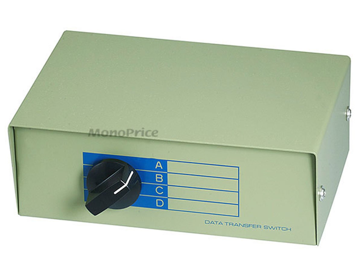
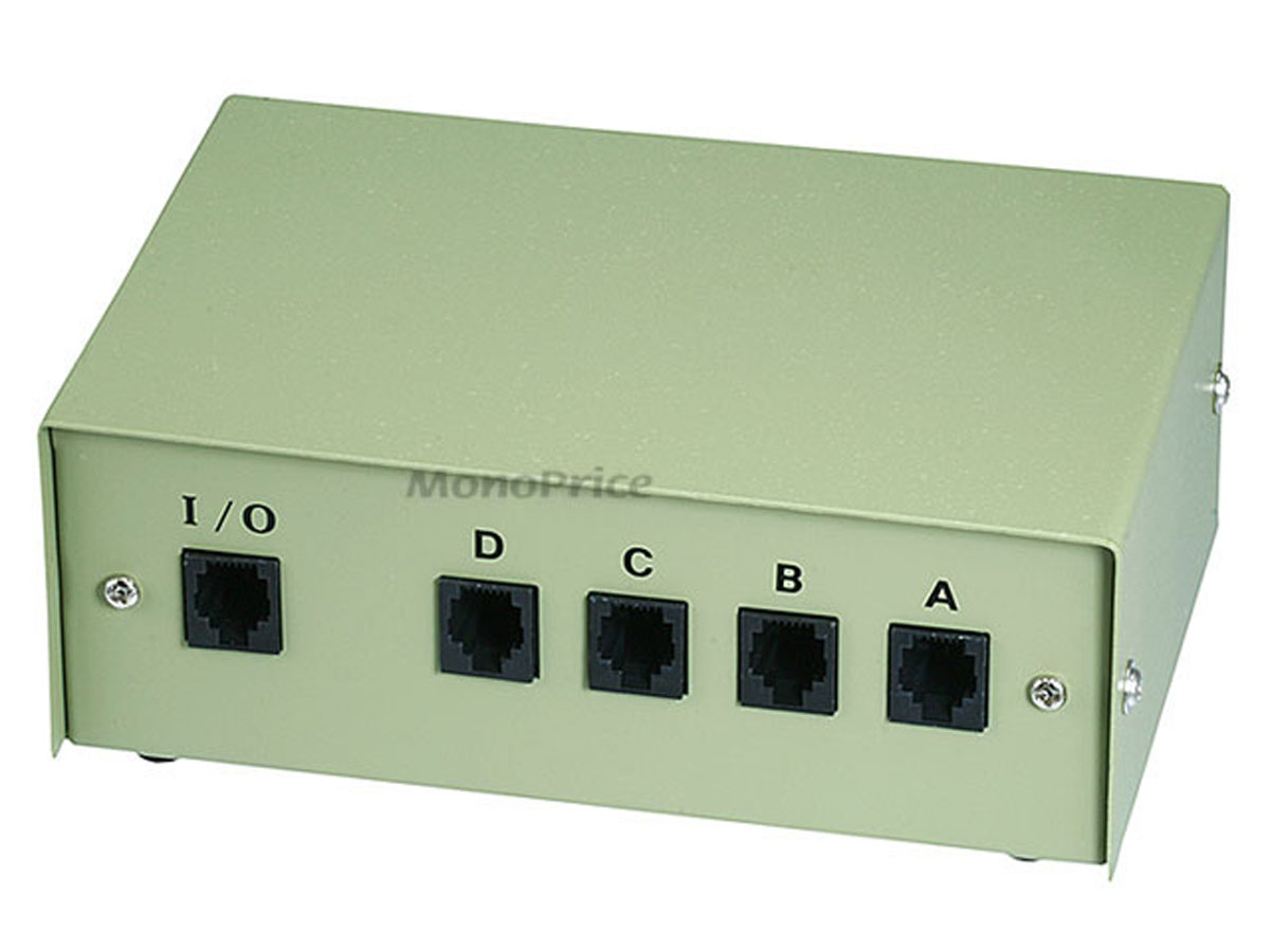
What´s the box, combining 2 3 of the ribbon controllers ?
How does it work ?
It's this box- about as simple as it gets. The ribbon uses a RJ-12 connector which is what old land-line telephones (remember those?) use - at least here in the US. I believe this box was intended for switching telephone lines.
The knob select 1 of 4 inputs that appears at the output. Each of my 3 ribbons are connected to an input and the output goes to the Kurz. I first tried some simple 2 to 1 "T" connectors that short each of the 6 lines of 2 ribbons together. It works but with long cable lengths funny things start to happen. Even with this switching box there is a slight glitch crossing between the upper 2 zones on the longer cable runs. Not surprising and not a big deal at this point. I think its more a capacitance issue than resistance.
This box is in serious need of a paint job.
-
This thread reminded me of a project I had on the back-burner. I wanted to convert this ribbon to work like a standard cv expression pedal substituting the RJ45 phone plug for a 1/4' TRS plug.
Unfortunately some measuring revealed that it"s actually 3 independent touch sensitive resistors/potentiometers, 1 per zone. Each is 5 kOhms. Kurzweil uses some clever logic handled by the processor to combine these 3 zones into a single long zone if desired.
There"s no easy way I can think of to do this in hardware. Changing the connections between zones would require cutting into the strip which I think would destroy the thing. I could use each zone for a different synth but as someone indicated on Theo"s 'abandonment' thread, some things just ain"t worth pursuing.
While I was extremely busy doing nothing last Friday I was actually contemplating another Seinfeld inspired thread. This idea turned out to be pretty damn cool and a ton of fun if I do say so myself.
[video:youtube]
-
Sheesh- you guys and your birthdays every year. No wonder you"re old.
Happy Birthday Michael!
-
Aw man, you mentioned this was coming up on Craig"s forum a couple of weeks ago and I was about to start a thread on your behalf.
No matter. Happy Birthday Paul- wishing you the best!
-
I hate it when people usewhen linking to websites; it's like "Teh Interwebs" or all of those Nord Lead jokes. Get off my lawn...!
That"s gold David, Gold!
-
Knotting to see here, move on:
http://www.thedogplace.org/images/Illustrations/breeding-miss-mate-158-Gammill.jpg
I"ll
to keep your dog nut things to yourself. -
Nord Lead ..........
If it doesn't say Hammond, it's just another clone ......
There, I said it.
Too bad there's nothing to clonk on.
-
Nadia
And her sister Nada...
...who turned out to be a big nothing.
-
There is no such thing as nothing.
What'd I just pay for?
[video:youtube]
-
Hmm. I have nothing to add, but by adding it I must have added something, even if it WAS nothing, thereby rendering my response potentially off topic.
I reported you. dB said there's nothing he can do about it. That made me feel better.
-
Thanks for nothing.
Oh gosh, it was nothing.
-
For clarity's sake, my previous post is the only one that's truly on topic.
Yeah, but without me you're nothing.
Also with me you're nothing.
-
Racist.
Don't worry - I'm not that fast.
-
Please be sure to stay on topic.


 :saber:


 to keep your dog nut things to yourself.

Reminiscing with this Bob Moog Interview
in The Keyboard Corner
Posted
During the virtual hang we talked about past NAMM hangs and I recalled the years (2 I believe) where Bob Moog paid a visit to our table. Coincidentally I came across this video on the Moog forum this morning.
[video:youtube]